Control and Safety Eng Ltd Case Study 1
Hanson Themalite, West Thurrock Bogie line, Separator and 5 Tonne Grab Safety Upgrade
This project was based on the safety requirements required to attain validation to BS EN ISO 62061 for a Bogie Line, Separator and 5 Tonne Grab on behalf of Hanson Thermalite.
The bogie line as an entirety consists of 15 bogie transport motors, this is split half-way into the north and south end each having 7 and 8 motors respectively. The two areas are split by Light Guard 14 and are made-safe by dual-redundant contactors controlled from the newcutter-line system.
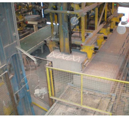
The separator tilting table area had recently been upgraded onto a safety PLC with the addition of new light curtains and laser scanners by a third party contractor but did not conform to current safety standards.
Additional work was also undertaken to ensure all control was taken from the existing Cutter Line fail-safe PLC and expanded it to include four new safety nodes for switching devices associated with the new scheme. The upgraded safety PLC was to be removed and all light curtains to be replaced with Leuze to enable proper validation. See diagram below. All new safety devices were to be connected to an AS-I SAFE system via DP/AS-I F-Links.
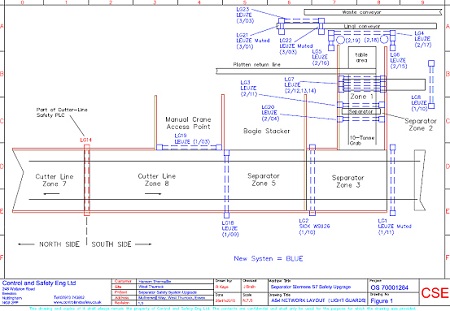
The image below shows the original bogie-line layout. There were a number of systems/devices acting in the same area which caused confusion. They were added to by systems having different safety-integrity, dependent on which access path was used to gain entry to the machine.
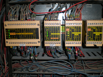
We suggested that a logical approach to the way the system was controlled would be applied. For example, the cutter line houses a Siemens S7 Fail-Safe PLC and the separator had recently had a PILZ PSS Fail-Safe PLC installed. In the middle of the two there was a hard-wired system which did not conform to current safety standards. We believed that the best option was to totally remove the hard-wired systems and move all of the safety control onto the existing cutter line Siemens S7-F Safety PLC. To gain production benefits we suggested further zoning of the bogie-line and separator in-feed.
The new equipment required included:
- Replacement of all existing (no-conforming) light guards for Leuze Compact Plus Type 4 range. Seventeen new light guards in total.
- Numerous solenoid locking Fortress gate switches and Pod keys
- Extra Siemens ET200S I/O remotely mounted using Profi-SAFE
The strategy to fulfil the functional safety requirements were to
- Agree the general safety and control overview of the safety requirements for the overall operation
- Define each safety-related control function (SRCF)
- Design SRECF using a workflow method
- Build control and safety system on site
- Verify component design to ensure it achieves its safety integrity level claim limit (SIL)
- Produce safety software design specification. Determine functionality in line with SRCF specification
- Install control and safety system
- Commission safety system using validation sheets
- Provide operator training.
Specification of safety related control systems
The emergency stop system had to work on a global basis with only one point of emergency stop reset which was located on zone 1 control desk. We ensured that there were a total of 10 e-stops located as follows:
- Zone 8 – bogie storage area
- Zone 8 – far side
- Zone 8 – existing gate 11
- Zone 3 – area e-stop next to hydraulic pack
- Zone 3 – bogie in feed panel mount e-stop
- Zone 2 – separator remote panel mount e-stop
- Zone 2 – skip launcher panel mount e-stop
- Zone 1 – panel mount e-stop (1)
- Zone 2 – panel mount e-stop (2)
- Zone 1B – e-stop
See diagram below
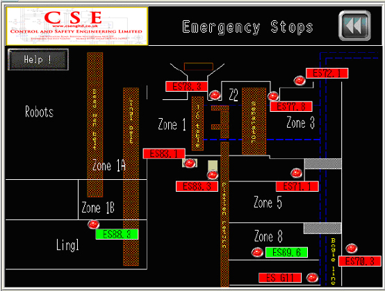
The emergency stop system was made to take priority over all safety zones. All zones were made to de-energise on an e-stop. In addition we ensured that the emergency stop must be reset before any zones could be reset.
SRCF ES1 stated ‘If any of the 9 e-stop buttons are pressed all zones must be de-energised to a safe state. When the safe state has been achieved a reset will only be allowed once all e-stop buttons are reset (twist to unlock)’
The e-stop functions were written purely in the software and the actual switching of the actuators were made to be carried out by the de-energisation of each individual zone in the software.
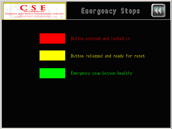
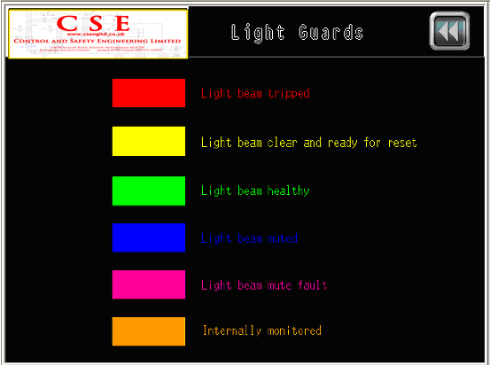
In addition to the SRECs there was a standard code written to communicate with an operator HMI. The information on the HMI informs which e-stop has been pressed and its current status using a colour code as follows
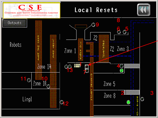
In discussion with Hanson personnel the system was split into 9 zones as follows
- Zone 1 – Turnover table, curing plate, platen conveyor, platen clamps, jockey wheel an separator feed conveyor
- Zone 2 – Separator feed conveyor and separator machine
- Zone 3 – Separator feed conveyor, ten-tonne crane, bogie ram 1, bogie ram 2 and separator transporter
- Zone 8 – Bogie ram 1, bogie ram 2, bogie line motors south, bogie line motor 1 and separator transporter
- Zone 5 – Bogie ram 1, bogie ram 2, bogie line motor 1 and separator transporter
- Zone 6 – Skip launcher and scrap belt
- Zone 1a – Lingl feed belt, dead man belt and Monica crane
- Zone 1b – Lingl feed belt, dead man belt
- Zone 10 – Dead man belt and Lingl machine
From the above you can see that various parts of the machinery overlap into different zones which meant that 15 individual fail-safe outputs were required.
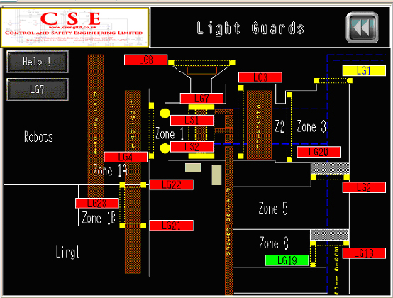
Each zoned area was considered individually and fail-safe outputs created. The following is an example
SRCF Z81 (Perimeter) stated ‘If an operator walks through light guard LG19 then the following fail-safe outputs must be safely de-energised’ –
Bogie motor 1,
Bogie rams 1 and 2,
Cutter line: Bogie motors south
Bogie transporter
‘Once LG 19 has been breached, a fail-safe memory bit within the PLC will be set to remember the point of access, thus only allowing a localised reset adjacent to LG19’
‘Once LG19 has been breached, both light guards LG14 and LG18 will be monitored by the safety PLC. If either LG14 and/or LG 18 are then breached these respective zone fail-safe outputs must be safely de-energised’
‘During de-energisation and re-energisation all respective fail-safe outputs will have their EDM circuits checked for a changeover time within 200ms’
SRCF Z82 (Perimeter) stated “If an operator opens Zone 8 far-side Fortress, then the following fail safe outputs must be safely de-energised:”
Bogie motor 1
Bogie rams 1 and 2
Cutter Line: Bogie motors south
Bogie transporter
“Once Zone 8 far-side Fortress has been opened, a fail-safe memory bit within the PLC will be set to remember the point of access, thus only allowing a localised reset adjacent to Zone 8 far-side Fortress”
“Once Zone 8 far-side Fortress has been opened, both light guards LG14 and LG18 will be monitored by the safety PLC. If either LG14 and/or LG18 are then breached there respective zone fail-safe outputs must be safety de-energised”
“During de-energisation and re-energisation, all respective fail-safe outputs will have their EDM circuits checked for a changeover time within 200ms” if an operator opens Zone 8
Below is the graphical representation of SRCF Z82
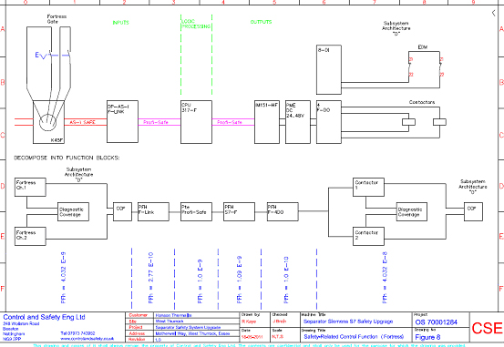
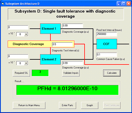
The figure below represents a system with single-fault tolerance incorporating diagnostic coverage. This layout can be applied to both Fortress Contacts shown in SSE 1 and the contactor outputs incorporating EDM signals.
The example below represents SSE 1 by the use of dual Fortress AmGuard contacts for input switching.
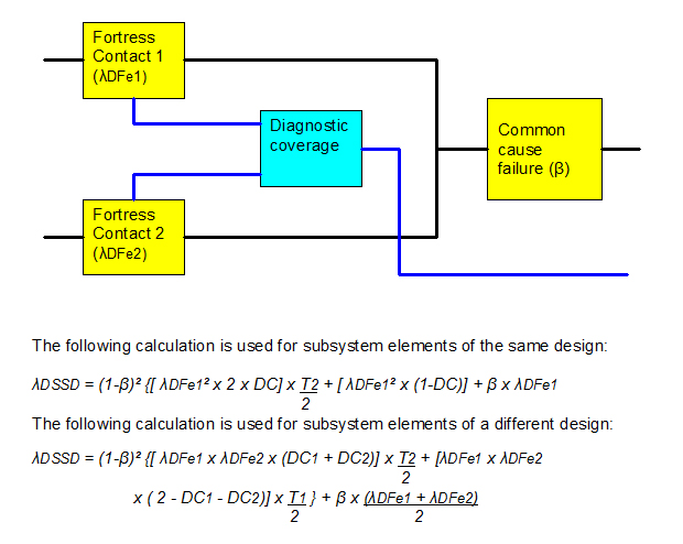
Where: T2 is the diagnostic test interval
T1 is the proof test interval (lifetime)
β is the common-cause failure
DC1 is the diagnostic coverage of subsystem element 1
DC2 is the diagnostic coverage of subsystem element 2
λDFe1 is dangerous failure rate of subsystem 1
λDFe2 is dangerous failure rate of subsystem 2
The susceptibility to common-cause failure within control function system design is estimated using Table F.1 of Annex F in BS EN ISO 62061. Using this method, β was estimated at 0.1 from an overall score of <35.
The diagnostic coverage (DC) is classed as “medium” and is taken from table 6 of BS EN ISO 13849:2006 “Safety of machinery – safety related parts of control systems”. From table 6, “medium” is taken as 90%-99%.
The calculation can be carried out from the following information:
Duty cycle, C = 2 operations/hour
T1 = B10 / C = 5,000,000 / 2 = 2,500,000
T2 = 2 times/hour = 0.5
λe = 0.1 x C/B10d = 0.1 (2 / 5,000,000)
= 4.0 E-8
λDFe = SFF x λe = 20% x λe = 0.2 x 4.0 E-8 = 8.0 E-9
β = 0.1
DC = 0.99
Calculation for Fortress gate “architecture D”
λDSSD = (1-0.1)² {[ 8.0E-9 x 8.0E-9 x (0.99 + 0.99)] x 0.5 + [8.0E-9 x 8.0E-9 2
x ( 2 – 0.99 – 0.99)] x 2.5E6 } + 0.1 x (8.0E-9 + 8.0E-9)
2 2
λDSSD = 8.0129 E-10
Duty cycle, C = 2 operations/hour
T1 = B10 / C = 5,000,000 / 2 = 2,500,000
T2 = 2 times/hour = 0.5
